
Category: Proportion/ratio

  • Beams and Ornaments

    This post describes supplies for the activities in Imago Mobiles and how to prepare them.

    First, you will need straight beams with regularly spaced holes. Ideally the center one will be labeled with a “0”, the two adjacent to the center labeled with “1”s, the next two out labeled with “2”, and so on. You can print out the following PDF, cut out the rectangular beam, and then use a hole punch to make the holes. Be careful to position the holes accurately! Positioning is key to balance.

    If you need or want more exactly-constructed beams, you can use the girders from many different construction sets, like Meccano (see for example item #2). Just be sure to use a beam with equally-spaced holes, and an odd number of them, so that there will be a single center hole.

    Second, you will need the ornaments. They can really be any objects that you want to hang, with one major proviso: they need to come in a limited number of types, and the weight of the ornaments (including the hooks!) of each type must be identical, and there must be a lightest type, a type that weighs twice as much, a type that weighs three times as much, and so on. Again, for emphasis, those weights should include the weights of the hooks.

    Here’s one way to achieve this. Print out five of the caterpillar ornaments below on the heaviest cardstock that will work with your printer. You must use the same weight of cardstock for all ornaments of a given kind. On a very sensitive scale (with 1-gram or better resolution), weigh the five ornaments together. Separately weigh five identical paper clips to use as hooks (you must use all identical paper clips as hooks for all ornaments for this to work!). Divide the measured weights by five to get the weights C of a single caterpillar and P of a single paper clip.

    Now make two test copies of the chrysalis (you will be throwing these two out), on the card stock that you want to use for this ornament. Cut them out and weigh them together, dividing the weight by two to get the test weight T of the chrysalis. Then the scaling factor for the final copies of the chrysalis is s = √((2C+P)/T). Calculate the scaling factor, rounding it to the nearest percent. Then print out several copies of the chrysalis, scaling by the computed scaling factor, on the desired card stock. Cut them out, and verify with your scale that a chrysalis with paper clip weighs the same as two caterpillars each with its paper clip.

    Follow the same procedure with the flower ornament, except use the formula s = √((3C+2P)/T) for the scaling factor. Verify that one of the scaled flowers with a paper clip weighs the same as three caterpillars with three paper clips. Finally, repeat with the butterfly using the formula s = √((4C+3P)/T) and check that a butterfly with paper clip weighs the same as four caterpillar-paper clip combinations.


    Now you have a supply of ornaments for making balanced mobiles. You can twist the paperclips however is helpful for making them into hooks, as long as you don’t break the paperclips or add any tape or anything else that would add weight. You can write down the scaling factor for each ornament, and as long as you use the same paper clips and the same cardstock, you can print and cut out as many ornaments as you like using those scaling factors.

    Finally, here are the PDFS for the four types of semicircular beams referred to in the post.


  • Imago Mobiles

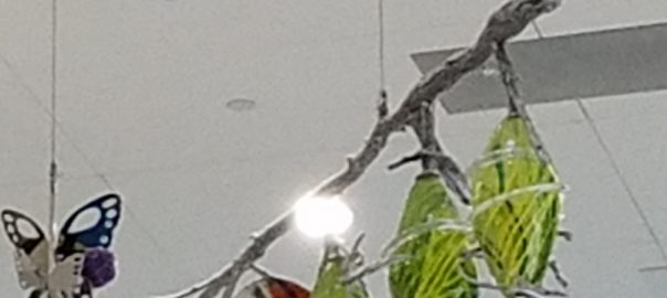
    Before you leave the Texas Discovery Gardens, be sure to appreciate Imago, the public art installation in the entrance foyer of the Gardens inspired by many aspects of the insect and plant life that abound there. But how can it also inspire us mathematically? There are likely many ways, but one important way is by illuminating the mathematics of balance. For example, take a look at the piece entitled Chrysalis.

    Notice that the branch on which the glass models are hanging is supported only at one point, so it is free to pivot, and yet it hangs perfectly horizontally instead of tilting to the right or left. (You can find a clearer picture on the designers’ website.)  In other words, it is in balance. What can you learn from this state of balance?

    You may know that we often use something called a “balance” for weighing things, so here’s a question you can ponder as you gaze at Chrysalis: which is heavier, two model chrysalises or one model chrysalis and two model leaves?

    It’s tempting to suppose that since the sculpture is in balance, those weights must be the same. Yet there’s more to it than that, making the situation even more interesting. To explore this, try the following activity: Start by hanging a perforated beam by its center hole (which may be labeled “0”). The beam should roughly balance horizontally, although it may be fairly wobbly. Next, get a supply of mobile ornaments; there should be different types, and they may also be labeled with numbers like 1, 2, 3, 4.

    Your goal is to hang an ornament or ornaments on each side of the perforated beam so that it will balance. (Don’t use the center hole, it is just for suspending the beam.)  Experiment with different configurations. What kinds of arrangements will balance?

    Likely you will discover that hanging two identical ornaments the same distance away from the center of the beam will cause it to balance. And that makes sense: if the two sides are the same, then they should balance each other out.

    But do the sides have to be the same in order for the beam to balance? Not necessarily. Try this: hang a “3” ornament in the hole immediately to the left of the center of the beam. Is there anywhere you can hang a “1” ornament to the right of the center to achieve balance?

    With some experimentation, you should find that a “1” ornament in the “3” hole just balances a “3” ornament in the “1” hole. And there are other combinations that will balance as well. Try a “2” ornament in the “2” hole against a “1” ornament in the “4” hole. Or put the same ornaments in the “2” and “3” holes on one side and in the “5” hole on the other side. Again, it should balance.

    Can you find a rule that will tell you when an arrangement will balance? Again, with some trial and error, you may be able to come up with this rule: take the number on each ornament and multiply it by the number of the hole it is in. Add up those products on each side. If you get the same answer on each side, then the beam should balance. For example,  a “2” ornament in the “3” hole and a “3” ornament in the “2” hole on one side should balance a “4” ornament in the “2” hole and a “1” ornament in the “4” hole on the other side, because 2×3 + 3×2 = 12 = 4×2 + 1×4.

    Another piece in Imago suggests a more advanced activity: Suppose instead of being straight, our beam were semicircular. It’s clear that if we hang the beam from its midpoint, it still balances by itself. But where should the other holes be so that the same rule as before will determine when ornaments hung on the semicircular beam will balance?

    There are two ways of going about this. The more challenging approach gives participants beams with just the “1” holes already punched, setting the goal of punching additional holes labeled “2”, “3”, etc. so that the rule will still hold. (Note that each participant or group will likely need multiple semicircular beams to work with, as it may take several tries to find the correct hole locations.) Alternatively, each participant or group can be supplied with three different possible hole-punched beams, and they can experiment to find which one works.

    In either case, participants should be able to discover that the holes punched at equal intervals in terms of horizontal distance will follow the same balancing rule as the holes on the straight beam did. This may be surprising, because then the holes are not distributed equally around the semicircle. For further mathematical challenge, at the high school level, it’s possible to use a little bit of trigonometry and similar triangles to demonstrate why it is only the horizontal spacing of the holes that matters.

  • Towering Gold

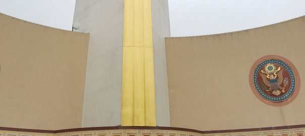
    Perhaps the most eye-catching feature of Dallas Fair Park is the gold-leaf wrapped Tower Building. Yes, that is real gold!

    Because of the allure and attraction of gold, our first math walk stop in Fair Park will be to ask, “How much is all of that gold on the Tower Building worth?” Before we go through the calculations, stop and take a moment to guess. Is it 1,000 dollars worth of gold if we crumpled it up into a solid nugget of gold? $10,000? A million dollars? Let’s figure it out.

    Since gold leaf is gold spread out thinly over an area, we need to figure out the surface area of the building that is covered by gold. We will model the front of the tower as a giant rectangle, the front of the eagle as another rectangle (which is of course a rough approximation, but it’s a small percentage of the entire gold area), and each wing as another rectangle. So we just need the dimensions of each rectangle.

    To estimate these dimensions, we can start with the height of the tower from the top of the frieze depicting the history of Texas to the feet of the eagle. We see that it is divided into nine vertical sections that appear to be equal in height. So we will focus on measuring the height of one of these sections, in particular, the bottommost section.

    If you stand dead center in front of the building, you will notice as you walk toward the building or away from it that when you are very close to the building, the frieze section appears taller than the first gold section above it, but when you are very far from the building the gold section appears taller. Move back and forth until you get to a spot where the two sections appear to be exactly the same height (lining a pencil up at about arm’s length so that it appears to match one of the sections in height and moving it up and down to compare to the other section can help).

    Once you’ve found such a spot, measure the distance to the center of the front wall of the building, and measure the height of the frieze directly with a measuring tape. (I get that the frieze is eleven feet high and that if I stand 22 feet away, the sections appear to be the same height.)

    Now take a look at the following diagram — it’s a vertical cross-section of the situation where your eye is at the point marked “I.” The fact that the two sections appear to be the same height means exactly that the two angles labeled theta are the same. Now with just the two dimensions and a little trigonometry, we can figure out the unknown height of the gold section. If you’ve learned some trigonometry, see if you can work it out.

    Here’s one way, in which we’ve cut the lower triangle in half with a horizontal line:

    The angle theta/2 has to have tangent 5.5/22 feet, so it is about 14 degrees. Therefore, angle MIA is about 42 degrees, and so leg MA is 22 feet times the tangent of 42 degrees, or about 19.8 feet. Therefore, the gold section BA is 19.8 – 5.5 = 14.3 feet, which we will round to 15 feet for ease of calculation (and because our eyeballing and measuring was very approximate, and the architect was more likely to use round numbers of feet for key measurements of the building).

    So the front section of the tower is roughly 9×15=135 feet tall, and we can directly measure how wide it is at the base. I got that it’s about 7 feet wide, but you should make your own measurement.

    Now, what about that eagle? We’ll just guess that it’s the same height as one vertical section of the tower; that shouldn’t be too far off. So we’re modeling the front of the eagle as another 15 foot by 7 foot rectangle, and the wings as 15 feet high. So all that remains is the length of the wings, which is the horizontal dimension of the two sides of the tower.

    But look closely at the sides of the tower. You will see a faint rectangular grid, with that horizontal dimension three and a half boxes wide. Moreover, two of the boxes side by side appear to form a square! It’s like the builders wrapped the building in graph paper to help us. Therefore, the horizontal dimension we want is 3.5/2 times the height of one vertical section, or about 27 feet.

    Adding up all of the sections of gold, there are 135×7 + 15×7 + 15×27 + 15×27 = 1,860 square feet of gold leaf on the building.

    How much gold does it take to make 1,860 square feet of gold leaf? Searching the internet, we can find one resource that tells us that 1000 “leaves” of gold cover 79 square feet  and weigh up to 23 grams. Dividing, the 1,860 square feet we need to cover would need 1,860/79 or about 23.5 groups of 1,000 leaves, which would therefore weigh 23.5×23, or about 542 grams.

    How much is that much gold worth, if it were crumpled up into one big nugget? To get that answer, we have to convert 542 grams into the unit that gold is bought and sold in: the troy ounce. A troy ounce consists of 31.1 grams, so the gold we’d need to cover the Tower Building would weigh 542/31.1, or approximately 17.43 troy ounces.

    To finish off, as of the time of this writing gold has been trading in a range around $1,300 per troy ounce for the past year. Therefore, the raw value of the gold on the Tower building is about 17.43×1,300, or $23,000. Is that more or less than you guessed? If it’s less, then it’s probably because gold leaf is so incredibly thin. By comparison, enough household aluminum foil to cover the Tower Building would weigh about 6,700 grams, or over twelve times as much. Combining that with the fact that gold is over seven times more dense than aluminum tells us that gold leaf is almost 100 times thinner than aluminum foil — yet it’s strong enough to last centuries on the outside of buildings!


  • Isosceles Esplanade

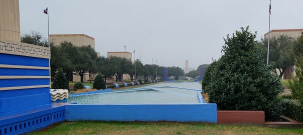
    Perhaps your stroll around Dallas Fair Park brings you to the Esplanade, a stately reflecting pool between Centennial Hall and the Automotive Building. The designers of the Esplanade for the 1936 World’s Fair had a difficulty, however: one end of the Esplanade is five to ten feet higher than the other, and of course water won’t stay with a slanted top; it always finds its level. So they had no choice but to install  some retaining walls (in this case, two) between one end of the Esplanade and the other, dividing the pool into three separate sections. Water flows over one of the retaining walls, creating a pleasant cascade.

    Rather than choosing to build the walls straight across the Esplanade, the designers chose to angle the walls, creating two long, sharp triangles pointing away from one end of the Esplanade and leading the eye toward the fountain in the lowest section of the pool. Looking at these triangles, it looks very likely that the two sides of each triangle are the same length, making them a special kind of triangle called an isosceles triangle.

    Looking at the resulting vista, one question that comes to mind is whether the engineers made the two triangles the same shape or not. The first thing to notice is that they can’t literally be identical shapes, because as you can see in the picture above, the nearer triangle is inset horizontally (along the shorter dimension of the pool) from the farther triangle. In other words, the base of the nearer triangle is shorter than the base of the farther triangle.

    But when we talk about things being the “same shape,” we don’t usually mean that they are identical. For example, in the usual sense, all squares are the same shape, but there are certainly different sizes of squares.

    Instead, what we usually mean when we say two things are the same shape is that you could scale one up to the size of the other and then the shapes would be identical. (The specific math word used for this is that the shapes are similar.) How can we tell if the two isosceles triangles in the Esplanade are similar?

    A little geometry tells us that two isosceles triangles are similar if their vertex angles (in this case, the “pointy ends”) are equal. So if we had a giant protractor and could set it down on those two points, we could figure it out. But unfortunately, we don’t have a giant protractor, and those two points are stuck in the middle of the pool; there’s no way to get to them without taking a swim (and breaking Fair Park rules)!

    To take a different approach, if those angles are equal, then the sides of the lower triangle will be parallel to the corresponding sides of the upper triangle. And in the photo above they do look parallel. So can we be sure? It looks pretty good even from another view:

    However, to be really sure, we should go back to the very definition of “similar:” every dimension of the two shapes should be in the same proportion. To check this, we should pace out the “horizontal” (along the short side of the pool) and “vertical” (along the long side of the pool) dimensions of each of the two walls. If you take equal-sized steps, you can just count your steps along the edges of the pond from when you are opposite one end of the wall until you are opposite the other. To get the short dimension, where the far, pointy end of the triangles are blocked from view by the tower on the left of the pictures, remember that those points of the triangles are lined up with the center line of the pool (and don’t forget that the farther wall extends farther to the left and right of the tower than then near wall — make sure you’re lined up correctly when you are pacing them off).

    When you have the two counts for each of the walls, divide the “vertical” count by the “horizontal” and see if you get the same quotient; that’s the definitive test of similarity. Give it a try!

  • Cooper Centennial Fountain

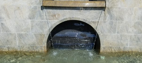
    Here’s a picture of one of the spouts of the Cooper Centennial Fountain in the Turner Quad on SMU campus. Do you notice anything of interest about the way the water falls? One thing that many people notice is that the water flows in toward the center on either side of the stream. Why would that be? The water is flowing straight ahead in the channel above the spout; why wouldn’t it continue to fall straight ahead, producing vertical sides to the sheet of falling water?

    Actually, just a few simple mathematical principles will show why the stream is compelled to become more narrow as it falls. Consider the amount of water that flows, say in one second, across any horizontal line in the image, say the bottom lip of the marble spout or one of the mortar lines in the wall behind the stream. That amount of water is proportional to the width of the stream times the speed at which the water is falling. On the other hand, the only source for water flowing across a line closer to the ground is the water crossing a line higher up; no new water is coming into existence within the stream. So the amount of water per second crossing any two horizontal lines must be the same (assuming water is being released over the lip at a steady rate, which it presumably is).

    Now here’s the key point: water, like anything else falling under the influence of Earth’s gravity, speeds up as it falls. So if the stream did stay a constant width as it fell, the amount of water crossing lower horizontal lines in a unit of time would be greater than the amount of water crossing higher horizontal lines. Since that’s impossible, the stream must become narrower as it falls. Mathematics forces it to.

    Now, you might ask, “Doesn’t this have something to do with surface tension or cohesion forces in the water?” And that’s a very reasonable question. There is in fact another logical alternative to the stream becoming narrower: the sides of the stream could remain vertical, but it could break up internally into numerous smaller substreams, perhaps eventually forming a mist. It’s surface tension and/or cohesion of the water that keeps it together in a single stream, and given that it remains a single stream, the simple math above tells us that stream must become narrower. (Even if the stream did break up, the “total width” in some sense of all of the substreams would of necessity decrease as the water fell, for exactly the same reason.)

    In fact, because matter is neither created or destroyed in the fountain, the math tells us more: the amount of narrowing must precisely offset the speedup of the water. Hence, a great activity that participants with a high school math background could do is actually model the contour of the sides of the stream. If you measure the speed of the water going over the lip, you can (using the effects of constant acceleration due to gravity), derive the speed of the water at any position below the lip, which in turn allows you derive the width of the stream at any height. Assuming (because of symmetry) that the stream remains centered below the lip of the spout, you can then derive an equation for the side contour of the fountain. Participants could graph their equations, and then superimpose their graphs over images of the fountain (or even the actual fountain, if the graphs are made in a waterproof medium). You should be able to achieve excellent agreement between the model and the actual contour of the water in this system. If you create any such images, please add a comment to this post telling us about it.

  • Blanton Student Services Building Interior

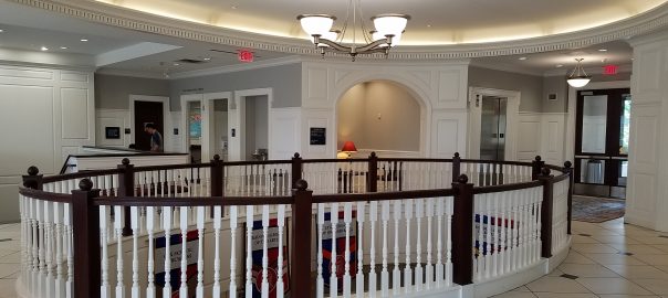
    As we’ve seen in other posts, the elegant architecture of the Southern Methodist University campus is a rich source for seeing mathematical concepts in action. One technique that architects use to unify the design of a building is to have a repeated feature or shape that recurs in multiple circumstances in the building (much as the 2:1 ratio does in the Nasher Sculpture building designed by Renzo Piano). AS you come into the interior of the Blanton Student Services building, are there any such architectural motifs that catch your eye? There are lots of possibilities that you might mention, but one is the ellipse that you will see in archways, in the ceiling, and in the large cutout between the first and second floors.To be most effective, the architect would want all of these ellipses to be the same shape; in other words, if you enlarged the floor cutout, would it match the ceiling, or if you shrank it down, would it match the elliptical archway? All circles are the same in this way, but there are different ellipses: some are long and skinny, and others are fatter, close to being circles. In fact, an ellipse is just a circle stretched out in one dimension, and it’s that amount of stretching that determines the shape of an ellipse.

    Mathematically, we can capture the amount of stretching in the ratio of the longer and shorter axes of an ellipse, or what are usually called the major and minor axes of the ellipse.If the ratio of the minor to major axes of two ellipses are the same, then they are the same shape (or similar in mathematical terminology).

    Suppose we wanted to determine if some of the ellipses in this building are similar in this mathematical sense? We would just need to calculate the ratio of the minor to major axis in each case. Finding that ratio is not difficult in case of the elliptical arch. You can use a tape measure all the way across the archway to get the major axis, and you can measure the height at the center of the archway and subtract the height along the side of the arch where it just begins to curve. That will give you half of the minor axis, because the top of the arch is half of an ellipse.

    But how can we calculate the axis ratio of the the elliptical hole in the floor? We likely don’t have a measuring tape of long enough to reach across the hole, and even if we did, especially with the railing, there’s no clear way to hold the measuring tape in place.

    Once again, proportionality comes to the rescue. We can make a “map” of the floor, and measure the axis ratio on our map. A map is nothing more than a diagram in which each measurement in the diagram is proportional to the actual object. So if our map is accurate and we take the axis ratio on the map, it will match the actual axis ratio.

    How can we make an accurate map? The square grid of the floor tiles can be our guide. Take piece of graph paper, mark a point in the middle of it, and walk to an intersection of the tile lines that is as close to the perimeter of the hole as possible. The point on the graph paper that you marked will correspond to the intersection you are standing on. Choose directions on the graph paper that will correspond to directions in the actual room. For example, “toward the exit” might correspond to “toward the right of the paper” and “toward the archway” (on the other side of the hole in the picture) might correspond to “toward the top of the page”.

    Then just walk around the hole in the floor from tile intersection to intersection, marking on the graph paper the correspoding grid segments that you traverse. Stay as closs as possible to the hole while staying on the grid. When you have finished, you should have a diagram that looks roughly like this.Now you can either sketchthe ellipse into the grid as I’ve done, or just use the points from the grid closest to the ends of the major and minor axes. In either case, you can just measure the two axes right from the map, and take their ratio. The axis ratio should closely match what you found for the archway, showing that indeed, the architects have used identical ellipses as a motif in this building.

    If you want to connect with the symmetry theme found in several other of the SMU tour posts, you can have participants notice that the map of the grid lines around the perimeter of the ellipse is composed of four identical sections that could be superimposed on each other by rotating and/or reflecting them; this situation occurs because each of the ellipse’s axes is also a line of mirror symmetry of the ellipse. It also has a twofold point of rotational symmetry at its center.